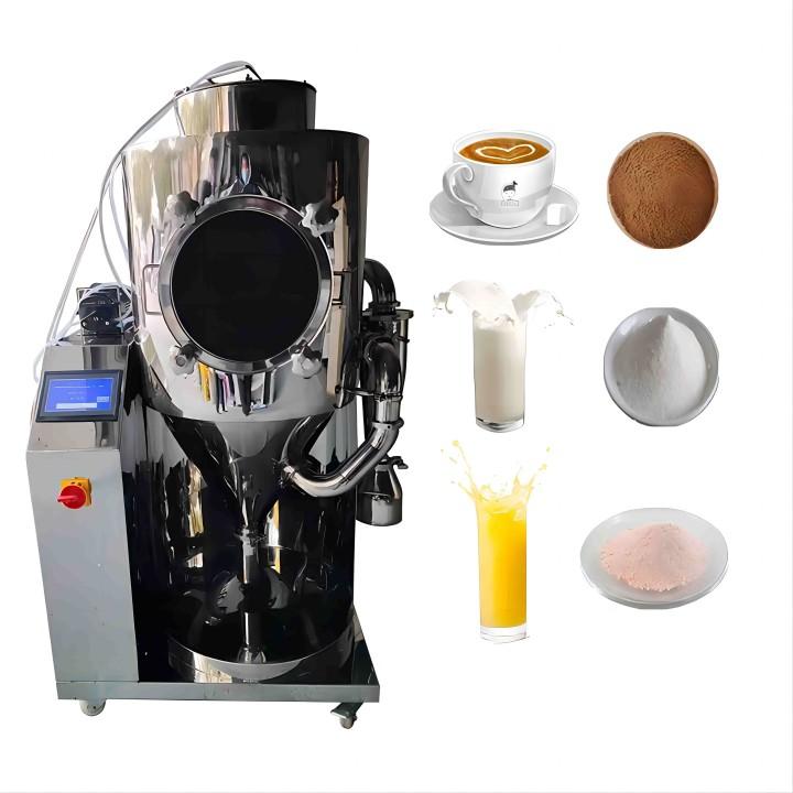
Vacuum Evaporator Concentration: Foaming, Temperature and Solvent Recovery
2026-10-23 16:18:21A buyer-focused guide to stable vacuum concentration, condensate handling and reproducible product quality.
A stable pressure reading does not guarantee stable concentration
A processor can reach the requested vacuum pressure yet see erratic boiling, a wet condenser outlet, or a concentrate that darkens before the target solids level is achieved. Another batch may appear quiet but concentrate unusually slowly. These outcomes are not contradictory. Pressure, vapor generation, heat input, liquid properties and condensation must work together, and a change in one part of the system can disturb the others.
At OLLITAL, we recommend treating vacuum evaporation as a linked process rather than evaluating the vacuum pump or vessel volume on its own. A useful equipment discussion starts with the feed composition and the intended product specification, then follows the liquid, vapor and condensate through the complete duty cycle.
1 | Specify absolute pressure, not an ambiguous “vacuum level”
Reducing the pressure above a liquid allows volatile components to boil at lower temperatures. That can help process heat-sensitive products, but the actual boiling behavior depends on liquid composition, dissolved solids and the local pressure. As solids concentration rises, boiling-point elevation, viscosity and changing vapor composition can all become relevant. A temperature listed for pure water at one pressure cannot automatically be used for an extract, syrup or mixed-solvent solution.
Buyers should require pressure to be reported as absolute pressure, for example in mbar(a) or kPa(a), or the precise gauge convention should be stated. “Vacuum -0.09 MPa” without a reference may hide differences in atmospheric pressure and instrument assumptions. Measure pressure near the process space when practical, and confirm that a remote vacuum-pump indication represents the vessel condition under actual vapor load.
Engineering distinction. A deeper vacuum may lower saturation temperature but increases the specific volume of vapor. At the same vapor mass flow this can raise vapor velocity and the risk of entrainment, as well as load the condenser and vacuum train differently. The target is a validated operating window, not the lowest number a pump can reach.
2 | Separate heating duty from the temperature displayed on the jacket
An external heat source must supply the sensible heat for warm-up and the latent heat removed through evaporation, along with losses to the surroundings. The heat-transfer driving force is not simply the heater setpoint minus room temperature: it depends on jacket-side conditions, liquid-side mixing and wall fouling. As product thickens, heat transfer can weaken even if the jacket temperature remains constant. A single high heater setting may create local overheating without producing the intended net evaporation rate.
Record at least the jacket inlet or heating-medium condition, the actual liquid temperature, vessel absolute pressure and condensate production rate during a trial. Compare the initial and final concentration phases separately. Apparent slowdowns near the end can reflect lower heat transfer, boiling-point elevation, feed behavior or increased viscosity, not necessarily a failing pump. Always apply the equipment manufacturer’s heating and pressure limits; do not use aggressive temperature changes to compensate for poor circulation.
3 | Foaming, bumping and entrainment require different responses
Foaming is sustained gas or vapor held within a liquid matrix; it is promoted in some feeds by surface-active compounds, proteins and other components. Bumping is more abrupt, with sudden bursts of boiling that may be triggered by rapid pressure reduction or unstable nucleation. Entrainment is the physical transport of liquid droplets with the vapor stream. The three can occur together, but they should not be treated as synonyms.
A foam blanket may rise into the vapor space, carry valuable concentrate into the condenser and contaminate recovered liquid. Bumping may cause intermittent slugs rather than a persistent foam layer. Excess vapor velocity can carry droplets even when a visible foam head is limited. If condensate is colored or contains suspended material, first consider carryover and sampling contamination rather than assuming the solvent itself changed color.
A controlled investigation uses the same representative feed while recording fill level, pressure ramp, evaporation rate, product temperature and separator condition. Possible process changes include slower pressure reduction, adjusted heat input, more available vapor disengagement space or a suitable mechanical separation design. Chemical antifoam should not be treated as a universal fix: it may change downstream product quality and must be approved for the application.
4 | Use observations to identify the most likely bottleneck
| What operators observe | Competing explanations | First comparison to make |
|---|---|---|
| Boiling becomes violent as vacuum is applied | Pressure ramp too fast; local superheating; formulation prone to bumping | Compare pressure and product temperature trends through start-up |
| Foam reaches the vapor outlet | Surface-active feed; too little headspace; high boil-up rate | Log fill level, heating duty and foam height at equal feed |
| Condensate becomes colored or hazy | Liquid entrainment; poor vapor-liquid separation; dirty receiver | Examine condensate and separator condition after approved shutdown |
| Evaporation slows late in the batch | Rising viscosity; fouling; boiling-point elevation; reduced heat transfer | Compare liquid solids, jacket-to-liquid differential and condensate rate |
| Vacuum drifts when production increases | Non-condensable ingress; condenser duty shortfall; excessive vapor load | Compare leak checks, coolant temperatures and running vapor duty |
| Recovered solvent volume seems low | Vapor bypass; receiver losses; condenser undersizing; calculation basis | Close the material balance and check vent/receiver boundaries |
5 | Condenser capacity is part of the vacuum specification
In a functioning concentration system the vapor path carries evaporated volatile components toward a condenser, where cooling removes latent heat and turns much of that vapor back into liquid. The receiver collects condensate, while an appropriately designed vacuum system handles non-condensable gases and any residual vapor. Cooling water or chiller temperature, flow and fouling can therefore have a direct influence on apparent vacuum performance and on solvent recovery.
A pump selected for the empty equipment’s ultimate pressure says little about performance while vapor is being produced. If the condenser cannot remove the entering vapor duty, excess vapor may reach the vacuum system; if non-condensable gas builds up, it can obstruct effective condensation. A robust inquiry should identify both the maximum expected vapor generation and the coolant supply conditions during the hottest local season.
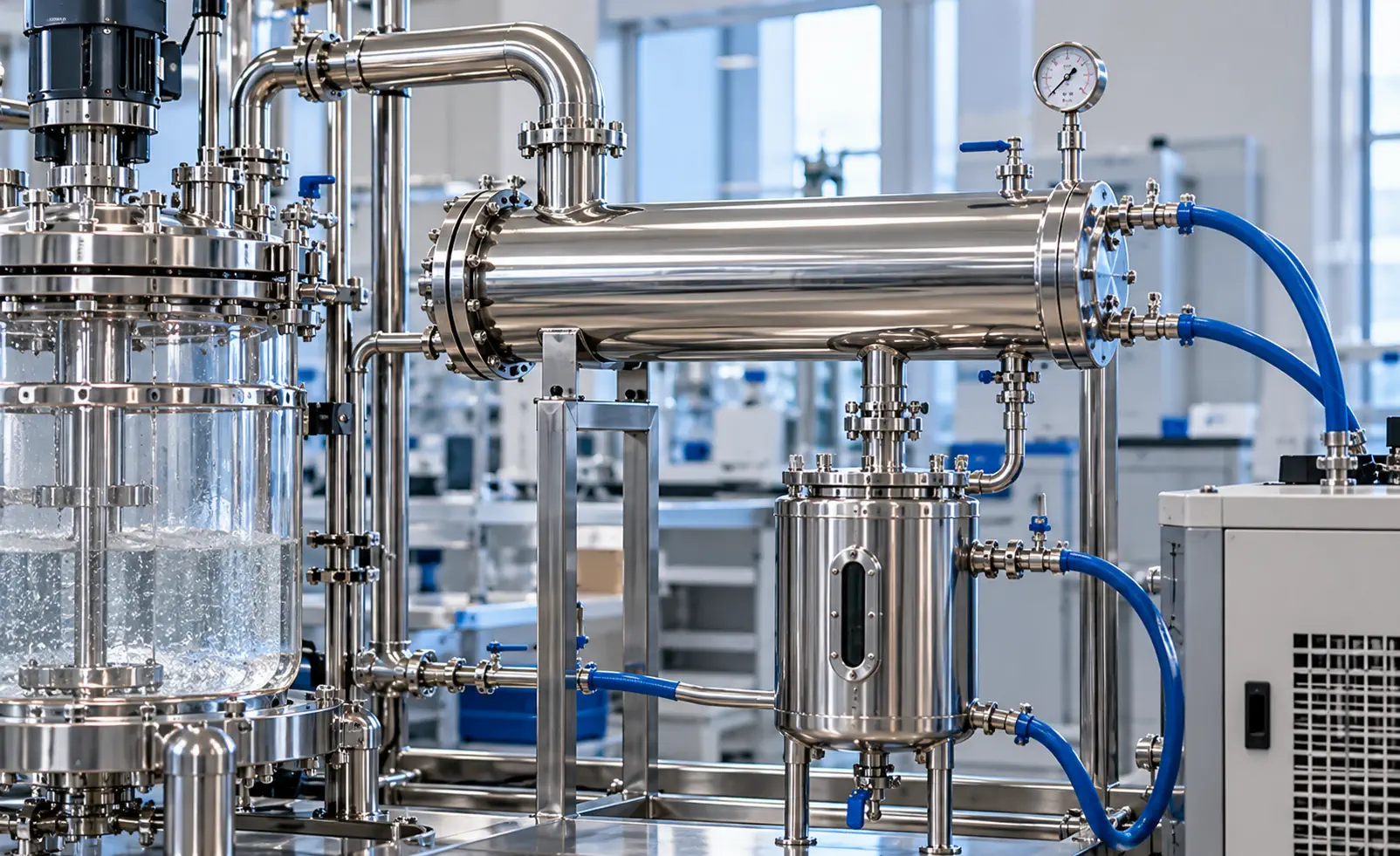
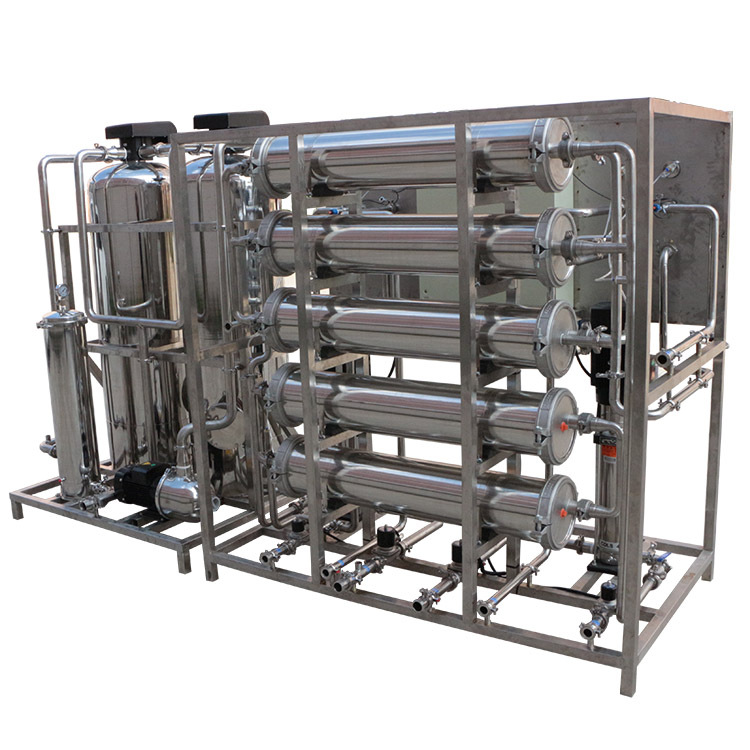
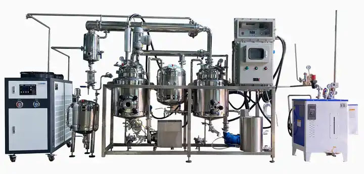
Figure 1 | Illustrative condenser and receiver connection for discussing cooling-water duty, vapor transfer and recovered liquid handling. Exact piping and instruments vary by project.
Do not confuse condensed mass with product recovery. If the feed contains multiple volatile components, the receiver composition may vary through the run, and recovered solvent may require testing or further separation before reuse. Likewise, traces of entrained concentrate can reduce condensate quality without indicating a change in condenser efficiency alone. For flammable solvents, evaluate enclosure, grounding, ventilation, electrical classification and emissions control through a site-specific safety review.
6 | A batch balance is more useful than a headline evaporation rate
Begin with a clear measurement boundary: feed charged, any additional liquid introduced, concentrate discharged, samples removed, recovered condensate and measurable hold-up. For a nonreacting system, total mass in should approximately equal total mass out plus remaining retained material within the uncertainty of the measurement. Solids balance can be more informative when the main volatile is water, provided the solids definition is appropriate and solids are not being lost by entrainment.
Illustrative relationship. If nonvolatile solids are conserved, feed mass x feed solids fraction approximately equals concentrate mass x concentrate solids fraction, after accounting for samples, entrained solids and hold-up. This is a calculation framework, not a guaranteed achievable concentration or a substitute for analytical testing.
At early concentration the liquid can be mobile and release vapor quickly; at higher solids it may thicken, foam differently or become difficult to drain. A batch-average evaporation rate conceals these stages. When suppliers quote an evaporation capacity in kg/h, ask which feed, initial and final solids, pressure, heating medium, coolant, and operating interval support that figure. Only like-for-like duty bases permit meaningful comparison.
7 | Protect the concentrate and document quality at the endpoint
The desired endpoint may be solids concentration, viscosity, density, a validated compositional marker, or a combination of measurements. A single temperature threshold is rarely enough to define it. Heat-sensitive materials can deteriorate through excessive residence time, local wall temperature or oxygen exposure even when nominal boiling temperature is low. The quality limit must be established for the real feed rather than copied from a general application description.
Sample consistently: define sampling time, mixing condition, cooling and container handling. For viscous concentrates, a warm surface sample can differ from a well-mixed bulk sample. Take care that the sampling method is compatible with vacuum and hot-liquid safety requirements. Record visual appearance and foam behavior alongside measured solids or viscosity, without presenting the visual inspection as a quantitative substitute.
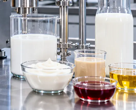
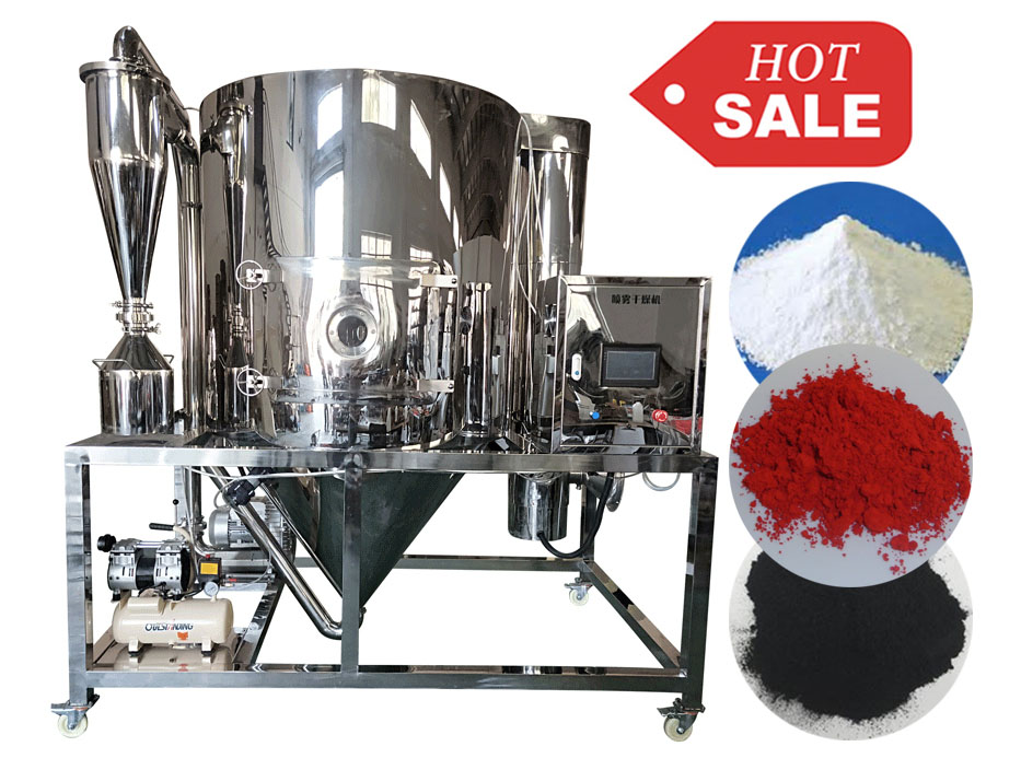
Figure 2 | Illustrative liquids of different appearances and apparent textures during sample review; not validated product test data or OLLITAL process results.
If a concentrated liquid is headed to a separate mixing, dilution, filling or drying process, include that downstream requirement in the specification. Pumpability, cleaning effort, discharge geometry, contact materials and any need for controlled cooling can constrain the practical endpoint. Do not assume that equipment used for the subsequent operation is included in the evaporator package.
8 | What the published OLLITAL product page does and does not confirm
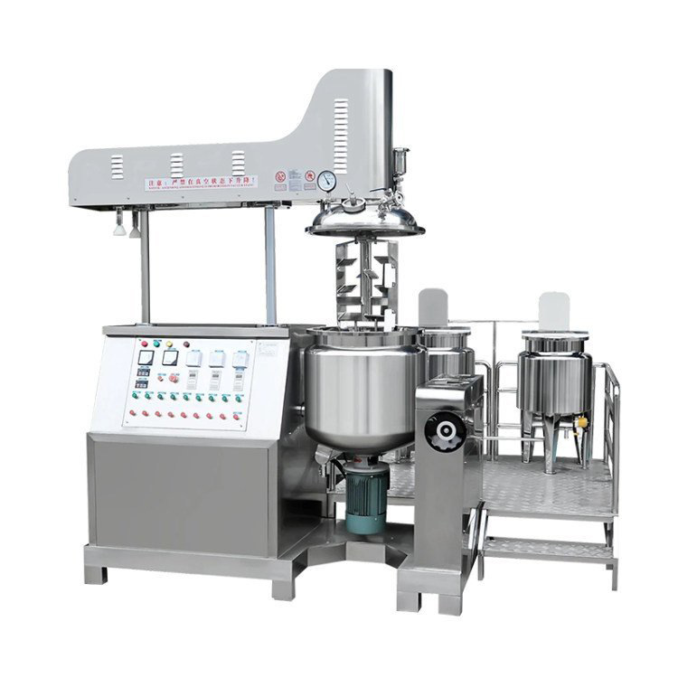
The OLLITAL spherical vacuum concentrator listing describes a concentration vessel, condenser, vapor-liquid separator and collecting tank as the main process sections. It also publishes a range of models, nominal capacities and heat-transfer areas. These are useful starting points for discussing an equipment family. They are not evidence of a specified evaporation rate, solvent purity, antifoam performance or product-quality result for every possible formulation.
Before purchase, confirm the actual offered model and documentation: drawings, pressure design basis, electrical and material specifications, wetted seals, suitable solvents, vapor path, condensate receiver, vacuum supply, cooling requirements and any cleaning features. The quoted scope must say whether the vacuum pump, chiller, control instruments, vapor-liquid separator and receiver are supplied together or separately. The supplier should not be asked to certify a process result from a catalog image alone.
9 | A compact RFQ checklist for vacuum concentrator buyers
| Purchaser input | What the engineer should return |
|---|---|
| Feed and solvent composition, feed volume, start/end solids | Duty basis, mass balance, expected batch stages and hold-up assumptions |
| Foaming, solids or fouling behavior observed in a pilot test | Proposed vapor disengagement and cleaning/inspection provisions |
| Maximum product temperature and acceptable residence time | Heating approach and required trial/validation questions |
| Available cooling water and utilities | Condenser heat-load assumptions and utility connections |
| Solvent recovery or emissions objective | Condensate receiver and vapor handling scope; appropriate safety review |
| Sampling, discharge and sanitation needs | Nozzle and transfer layout, compatible materials and maintenance access |
10 | Commission for repeatability, not just first-batch appearance
A practical acceptance trial should follow a defined sequence: inspect clean and dry hardware, verify relevant gauges and temperature sensors, establish cooling and vacuum readiness, charge a documented feed, apply a controlled pressure/heat ramp and record steady and late-batch behavior. Collect the condensate and final concentrate under a documented boundary. Inspect the separator and receiver following the permitted shutdown procedure and compare the measured outcomes with acceptance questions agreed in advance.
Do not intervene in an operating hot vacuum vessel simply to inspect foam or clear a line. Use designed observation, sampling and isolation points and follow the appropriate depressurization, cooling and lockout procedure. For solvent-containing service, the operating review must cover vapor flammability, potential ingress of air and site rules for handling condensate and ventilation. These topics determine the suitable hardware package and cannot be solved through SEO copy or a generic process recipe.
The purchasing decision: match the whole evaporation train to the real feed
A satisfactory vacuum evaporator is not the unit with the deepest attainable empty-vessel vacuum or the largest nominal tank. It is a configuration that can remove the intended volatile load, manage foaming and entrainment, protect the concentrate, collect vapor safely and run at the available utility conditions. A realistic process brief and one documented trial typically provide more purchasing value than a long list of unrelated accessories.
At OLLITAL, we recommend sharing feed composition, starting and target solids, batch size, vapor recovery objective and observed foam or viscosity changes before confirming the evaporator package. Our discussion can then focus on the actual process boundary, equipment arrangement and a measurable commissioning plan.
See the OLLITAL spherical vacuum concentrator for the published equipment family. If concentration follows a liquid-extraction stage, review the OLLITAL ultrasonic extraction system as a separate upstream process reference.
Planning a vacuum concentration or solvent-recovery project? Share the liquid composition, heating/cooling utilities and target concentrate quality. Contact OLLITAL