Foam Control in Microbial Fermentation: Foam Sensors, Antifoam Dosing and Exhaust Filter Protection
2026-10-15 17:03:17The point where foam becomes a process problem
A layer of bubbles is not automatically a failed fermentation. Microbial broths can foam because gases are sparged into liquid that contains proteins, polysaccharides, surfactants or biomass. But when that foam rises toward the headspace outlet, it can become a process-control and contamination-risk issue rather than a cosmetic one. Foam can interfere with gas disengagement, wet an exhaust element, disturb sensors, and make a run harder to reproduce.
For process teams, fermentation foam control is therefore a balance between the biology, the gas-liquid system and the sterile boundary. Adding antifoam may suppress visible foam, yet it does not necessarily solve the reason foam is forming. An effective approach asks three questions: What is driving the foam? How is the condition detected? And what secondary consequences can the response create?
1. Why identical vessels can show different foam behavior
Foam formation depends on more than vessel volume or agitation speed. Culture medium and organism physiology influence surface-active compounds; sparger characteristics influence bubble size; aeration and mixing influence how bubbles are dispersed; and working volume controls available headspace. A recipe that stays quiet during early growth can foam strongly as biomass, proteins, viscosity or feed composition changes.
The same fermentation may also behave differently after sterilization, inoculum preparation or feed changes. Residual cleaning chemicals, a new raw-material lot or different gas settings can change foam persistence. That is why a foam alarm should be interpreted alongside the current batch stage rather than against an isolated threshold.
During scale transfer, hydrodynamics change. Gas rate per unit volume, impeller arrangement, liquid height and surface area are not preserved simply by matching motor RPM. Before assuming that the same antifoam strategy will transfer unchanged, record gas supply, broth behavior and foam response across the full process window.
2. Foam height is a risk signal, not a complete diagnosis
A visual foam layer tells the operator something is accumulating at the gas-liquid interface. It does not on its own distinguish increased gas entrainment, a change in culture chemistry or a failing exhaust pathway. A stable foam layer below the outlet may be manageable under an approved process. Repeated carryover toward the exhaust, an unexpected pressure response, or a persistent foam alarm deserves prompt investigation according to the facility procedure.
Headspace matters because it provides room for gas to disengage before reaching the outlet. When working volume rises through feeding, that margin can shrink. Foam that was not previously close to a gas outlet may become critical later in the batch. Sampling and transfer configurations also determine which openable interfaces must remain protected.
3. Foam sensor, controller and dosing pump: three different jobs
An in-vessel foam electrode can provide a contact-based indication that foam has reached a particular location. The controller may interpret that contact, apply configured delays or limits, and command a peristaltic pump to add antifoam. The detector identifies a condition at its location; it does not directly measure the total quantity of foam in the vessel or establish the cause.
Probe fouling, condensate, conductive deposits and shifting liquid splashes can create misleading signals. Poor positioning can miss intermittent foam or react too often to transient splashing. Any automation therefore needs an agreed alarm strategy, a documented sensor-check method, and a clear response if the signal is inconsistent with the process trend. Antifoam dosing should be verified by delivered volume or mass where practical, not inferred from a pump command alone.
OLLITAL product information for the OLT-100-M1 glass fermenter lists a defoaming electrode and automatic defoamer addition through a peristaltic pump. Its OLT-500-C1 stainless fermentation family also lists foam-control functions. These listings show available capability; actual supplied probe, pump, head arrangement and control sequence must still be checked against the ordered configuration.
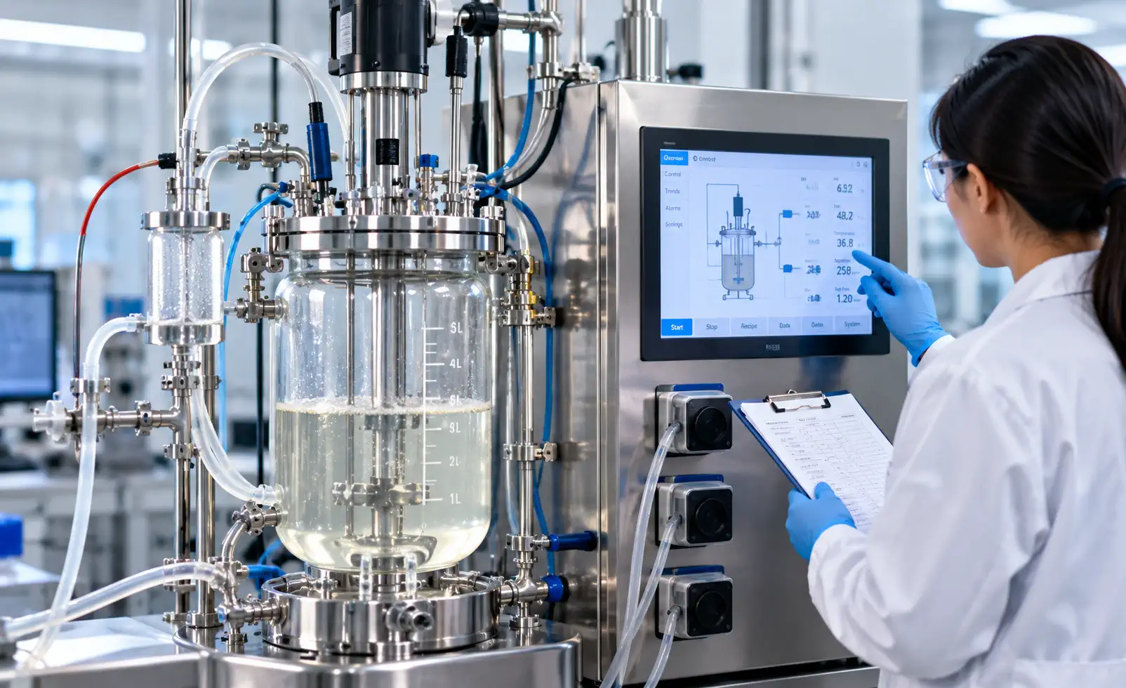
Figure 1. Illustrative operator monitoring a fermentation controller and associated tubing. Actual foam-sensor type and pump programming are model-dependent.
4. Antifoam is a process material, not only a corrective liquid
Chemical antifoams reduce bubble stability by changing interfacial behavior, but they can also influence oxygen transfer, gas holdup, broth rheology, probe behavior, downstream separation and cleaning. Different formulations do not behave identically. The appropriate choice depends on the organism, medium, process goal, product-contact constraints and any downstream purification requirements.
Automatic dosing is useful when the foam pattern is repeatable, yet excessive pulses can hide a root-cause problem. If the system is repeatedly demanding antifoam, the investigation should review gas flow, agitation, feed composition and measured delivered dose. Raising the dose limit without understanding the source may alter the biological environment. A validated dose envelope and recorded additions help distinguish a controlled batch from one that simply looks less foamy.
The dosing line is also part of the sterile process boundary. Bottle preparation, tubing compatibility, pump-head condition, check-valve integrity where applicable, and connection method all matter. A sound foam-control configuration considers both the controller logic and how the antifoam actually reaches the broth.
5. Why exhaust filter protection belongs in the same discussion
Foam can carry liquid droplets, cells and product constituents upward. If these reach a sterile exhaust filter, wetting or fouling may change flow resistance and compromise reliable venting. A filter may be correctly specified for gas service but still be vulnerable to liquid carryover. This is one reason that headspace geometry, exhaust-line routing, condensate handling and filter protection should be reviewed together rather than treated as unrelated accessories.
An elevated vessel pressure, declining vent capacity, wet downstream surfaces or unexpected condensate should not be diagnosed from one symptom alone. Potential explanations include foam carryover, water condensation, blocked or improperly installed components, changing gas demand, or an instrumentation issue. When abnormal pressure or impaired venting is suspected, follow the manufacturer and facility safety procedures; do not open a hot or pressurized sterile connection to “check” the filter.
Depending on the actual configuration, an exhaust condenser or suitable protective arrangement can reduce liquid loading. But the existence of a condenser on one product page does not prove that every delivered fermenter has the same exhaust path. Before purchasing equipment, request a clearly marked gas and exhaust schematic identifying components included in the proposed supply.
6. Aeration and agitation: solving one limit can create another
Increasing airflow or agitation may improve oxygen supply in some processes while also increasing bubble generation, gas-liquid contact and visible foam. Conversely, reducing airflow to suppress foam may restrict oxygen transfer. This is why foam-control changes should not be optimized independently of dissolved oxygen, agitation, gas composition and culture performance.
The right review compares time-aligned data: DO trend, airflow or mass-flow reading, rpm, feed stage, foam-alarm timing, antifoam additions, vessel pressure if measured, and any observed changes in broth behavior. A falling DO reading and rising foam signal do not prove that the foam caused oxygen limitation; they may reflect a common change in process demand or different concurrent mechanisms.
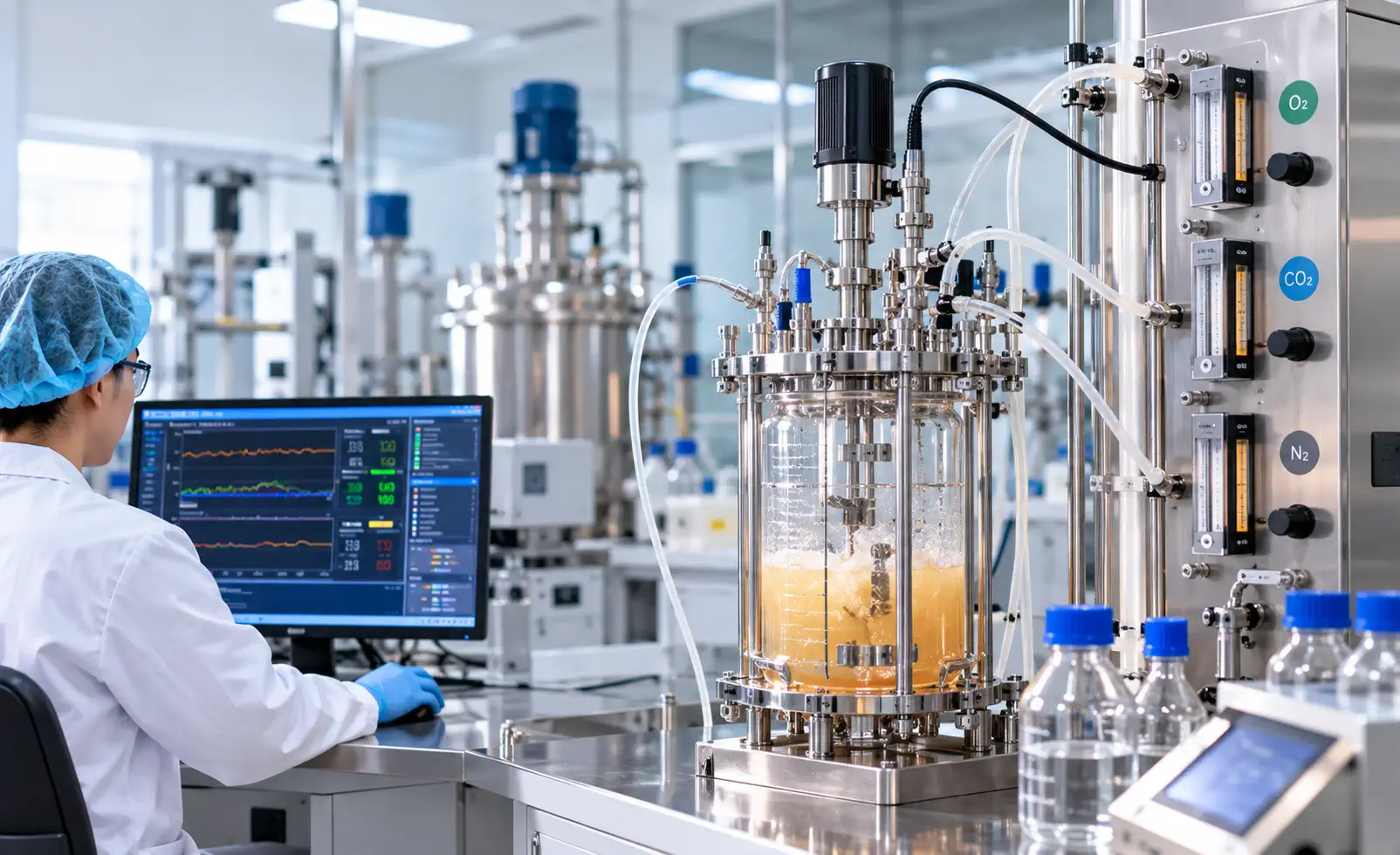
Figure 2. Illustrative monitoring of gas-flow and cultivation variables. Shown as a process context image, not as an OLLITAL standard gas-supply specification.
7. A useful deviation record separates symptom from cause
A practical investigation starts with what the operator observed, then checks independent evidence before changing an operating strategy. The following matrix is a discussion tool, not a prescribed operating recipe.
| Observation | Possible interpretations | Evidence to check |
|---|---|---|
| Frequent foam alarms | Persistent foam, splashing or fouled probe | Sensor condition, actual foam level, feed phase, gas and rpm changes |
| Repeated antifoam pulses | Delivery error, growing foam load or narrow control settings | Pump calibration, antifoam usage history and approved dosing limits |
| Foam near exhaust | Reduced headspace, stronger gas entrainment or liquid carryover | Working volume, gas settings, exhaust configuration and pressure trend |
| DO shift after dosing | Changed gas-liquid transfer or unrelated process change | DO verification, dosing timestamp, gas and agitation records |
| Pressure deviation | Vent restriction, wetting, valve state or sensing fault | Approved pressure/vent investigation under the facility safety procedure |
The objective is traceability. One apparent “foam problem” can be a sensor problem, a dosing-line problem, a gas-delivery problem or a process-formulation change. Investigations are stronger when they use independent measurements and preserve the complete event sequence.
8. What to confirm on an OLLITAL fermentation configuration
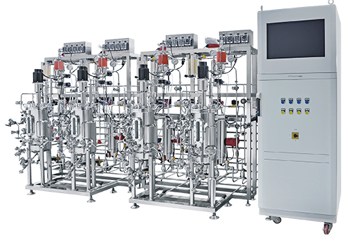
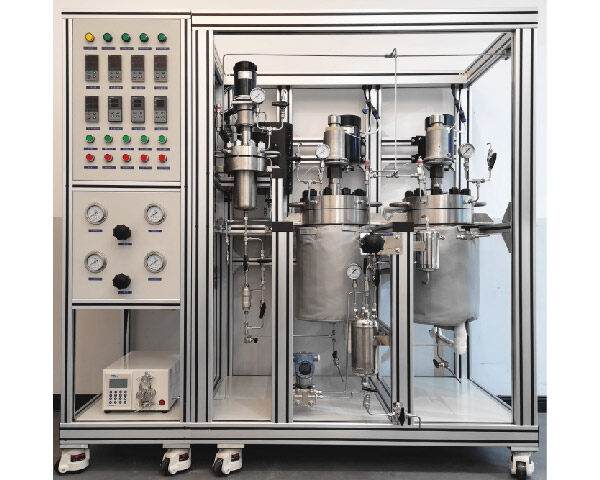
Product pages can establish whether a function is offered, but they do not define every connection on a specific shipped system. For a laboratory installation, review the glass bioreactor configuration for foam sensing, pump allocation, gas supply and sterilizable parts. For a process vessel, review the stainless steel fermenter platform for the corresponding probe, pump and headspace design. Optional components must be distinguished from standard elements.
When discussing a quotation, identify the process medium, organism class, working-volume range, gas supply, expected foam tendency, exhaust filter requirements, antifoam formulation and sterilization method. Ask for the intended foam-probe location, addition-point arrangement, hose and pump material compatibility, exhaust-path drawing, control logic and evidence of the proposed configuration. A product photo alone cannot answer those questions.
It is also worth confirming which data are actually retained: alarm events, pump-command history, delivered dose where supported, gas-flow values and timestamps. If the system must support later process comparison, the data structure should be considered during engineering rather than after installation.
9. Four questions that improve a foam-control RFQ
Is automatic foam detection the same as automatic foam elimination?
No. Detection indicates foam has reached the sensing point. A pump or mechanical device then responds according to its configured strategy. The extent of foam reduction depends on the formulation, equipment and process state; an alarm-clearing event alone does not prove the entire process is optimized.
Can antifoam remove the need to monitor oxygen transfer?
No. Antifoam may affect mass transfer, while changes in gas flow and agitation may affect both oxygen supply and foam generation. DO, gas and dosing records should be reviewed together.
Does a sterile exhaust filter guarantee protection against foam carryover?
No. Filtration and protection against liquid wetting are different questions. Filter location, allowed service conditions, exhaust-line design and contamination-control procedures all matter.
What should be sent to the equipment supplier?
Send the working-volume range, broth and gas characteristics, expected foam load, antifoam restrictions, planned sterilization, control and data needs, and the exhaust-path interfaces. State which elements are essential and which are options for the supplier to evaluate.
Conclusion: control foam without losing sight of the process
Effective bioreactor foam control protects more than the visible liquid surface. It links culture chemistry, aeration, headspace, sensing, antifoam delivery and the sterile exhaust boundary into one reviewable operating strategy. A well-designed system makes foam events measurable, dosing accountable and unexpected changes easier to investigate without sacrificing oxygen-transfer or contamination-control goals.
At OLLITAL, we recommend reviewing the real process envelope before selecting a foam-control arrangement. Compare the bioreactor and fermentation range with your medium, gas, sensor and exhaust requirements, then contact OLLITAL to discuss a configuration that fits the intended operating workflow.